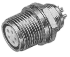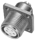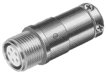
R01, R03, andR05 Series
|
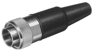
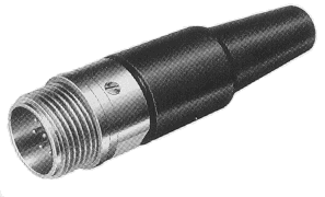
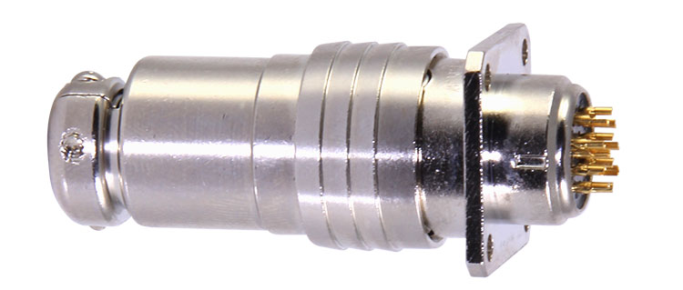
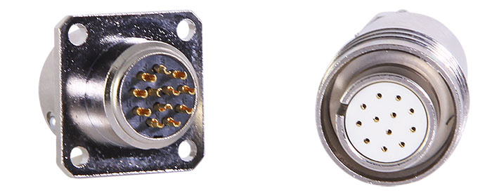
R01, R03 and R05 series multipin circular connectors are small
in size and high in reliability suitable for miniature and high
density electronics equipment. R01 series is water resistant and
designed for applications in Mobil radios and outdoor small electronics
equipment.
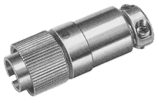
R01, R03 series are threaded coupling and R05 series is bayonet
lock coupling. |
 Specifications:
No. of Contacts: 2 to 12
Vibration, Moisture and Corrosion Resistance: MIL-STD-202E
Temperature range: -25°C to +85°C
Materials
| Principal Parts |
Materials |
Plating |
| Shell |
Brass & Zinc Alloy |
Nickel |
| Contacts |
Copper Alloy |
Gold (Nickel Based) |
| Insulation |
PBT Resin qualified to UL Standard (Class 94V-0) |
Part Numbering System
R01 Series
R01 - 01P 9 - 8 F
| R01 |
Series |
| 01P |
Shell Style (01P: Plug, R: Bulkhead Receptacle,
02R: Bulkhead Receptacle, 06J: Jack) |
| 9 |
Insert Size |
| 8 |
No. of Contacts 6 and 8 |
| F |
Contact Type (F: Female, M: Male) |
R03 & R05 Series
R03 - PB 10 3 F
| R03 |
Series |
| PB |
Shell Style (R: Bulkhead Receptacle, PB:
Plug, RB: Flange Mounting Receptacle, JB: Jack) |
| 3 |
No. of Contacts 2, 3, 5, 6, 8, 12 |
| F |
Contact Type (F: Female, M: Male) |
| 10.5 |
Inner Diameter |
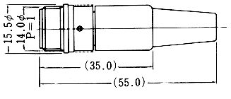
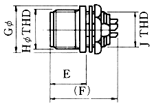
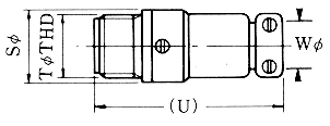
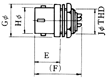
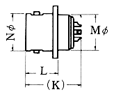
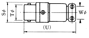
Dimensions (R01)
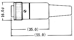
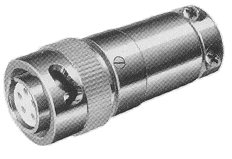
Plug
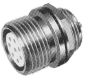
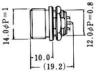
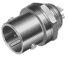
Bulkhead Receptacle
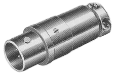
Jack
Dimensions (R03)
Plug
Bulkhead Receptacle
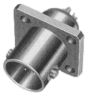
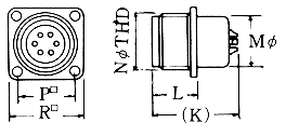 Flange Mount Receptacle
Jack
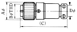
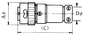
Dimensions (R05)
Plug
| Series |
No. of Contacts |
Dimensions (mm) |
| A |
B |
C |
D |
E |
F |
G |
H |
J |
K |
L |
M |
N |
P |
R |
S |
T |
U |
W |
| R03 |
2, 3, 5 |
12.0 |
10.5
P=0.75 |
32.0 |
5.2 |
9.0 |
18.0 |
12.0 |
10.5
P=0.75 |
9.0
P=0.5 |
18.0 |
9.5 |
9.0 |
10.5
P=0.75 |
10.5 |
15.0 |
12.0 |
10.5
P=0.75 |
32.0 |
5.2 |
| 6, 8 |
15.5 |
14.0
P=1 |
34.0 |
6.2 |
9.0 |
18.0 |
15.5 |
14.0
P=1 |
12.0
P=0.8 |
18.0 |
9.5 |
12.0 |
14.0
P=1 |
13.0 |
17.5 |
15.5 |
14.0
P=1 |
34.0 |
6.2 |
| 12 |
20.0 |
18.0
P=1 |
39.0 |
10.5 |
9.0 |
18.0 |
20.0 |
18.0
P=1 |
16.0
P=0.75 |
18.0 |
9.5 |
16.0 |
18.0
P=1 |
17.0 |
22.5 |
20.0 |
18.0
P=1 |
39.0 |
10.5 |
Bulkhead Receptacle
Flange Mount Receptacle
Jack
| Series |
No. of Contacts |
Dimensions (mm) |
| A |
B |
C |
D |
E |
F |
G |
H |
J |
K |
L |
M |
N |
P |
R |
S |
T |
U |
W |
| R05 |
2, 3, 5 |
13.0 |
- |
32.5 |
5.2 |
9.5 |
18.0 |
12.0 |
9.5 |
9.0
P=0.5 |
18.0 |
10.5 |
9.0 |
9.5 |
10.5 |
15.0 |
12.0 |
9.5 |
32.0 |
5.2 |
| 6, 8 |
16.0 |
- |
34.5 |
6.2 |
9.5 |
18.0 |
15.5 |
12.3 |
12.0
P=0.8 |
18.0 |
10.5 |
12.0 |
12.3 |
13.0 |
17.5 |
15.5 |
12.3 |
34.0 |
6.2 |
| 12 |
20.0 |
- |
39.0 |
10.5 |
9.0 |
18.0 |
19.5 |
16.3 |
16.0
P=1 |
18.0 |
10.5 |
16.0 |
16.3 |
17.0 |
22.5 |
20.0 |
16.3 |
39.0 |
10.5 |
Mounting Hole Dimensions
| Flange Mount Receptacle |
Bulkhead Receptacle |
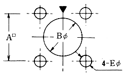 |  |
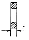
Max Panel |
| No. of Contacts |
A |
B |
C |
D |
E |
F |
| R01 |
R03 |
R05 |
| 2, 3, 5 |
10.5 |
9.2 |
9.2 |
8.4 |
2.2 |
- |
2.0 |
1.6 |
| 6, 8 |
13.0 |
12.2 |
12.2 |
11.2 |
2.2 |
1.6 |
2.0 |
1.6 |
| 12 |
17.0 |
16.3 |
16.2 |
14.7 |
2.8 |
- |
1.6 |
1.6 |
Insert Arrangements
| Insert No. |
6 - 2 |
6 - 3 |
6 - 5 |
9 - 6 |
9 - 8 |
12 - 12 |
| No. of Contacts |
2 |
3 |
5 |
6 |
8 |
12 |
| Insert Arrangements |
 |
 |
 |
 |
 |
 |
| Current Rating |
2A |
2A |
2A |
2A |
2A |
2A |
Voltage Rating
(AC. V. rms) |
300V |
300V |
150V |
300V |
200V |
300V |
Withstand Voltage
(AC. V. rms) |
900V |
900V |
500V |
900V |
700V |
900V |
| Contact Resistance |
DC3V 1A 8mW
max. |
| Insulation Resistance |
DC500V 1,000mW
min. |
| Applicable Wire |
A.W.G. # |
AWG #24 |
AWG #24 |
AWG #24 |
AWG #24 |
AWG #24 |
AWG #24 |
| Square |
0.3mm² max. |
0.3mm² max. |
0.3mm² max. |
0.3mm² max. |
0.3mm² max. |
0.3mm² max. |
| Wire Diameter |
0.7Ø max. |
0.7Ø max. |
0.7Ø max. |
0.7Ø max. |
0.7Ø max. |
0.7Ø max. |
|


